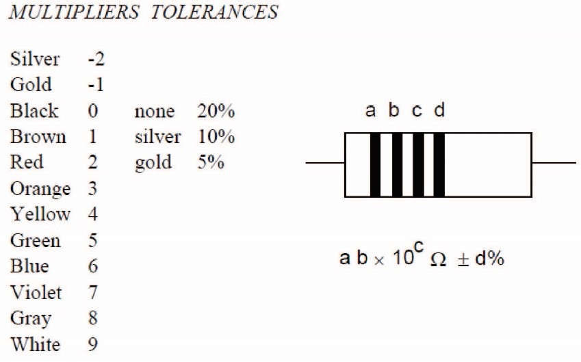
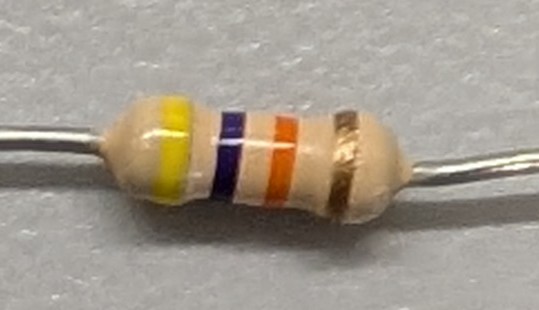
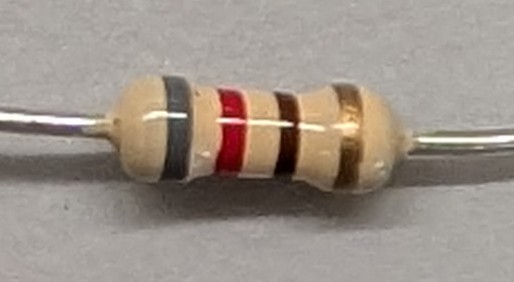
Resistors are marked with (typically) four colored bands. These bands provide a code that can be used to determine the fvalue of the resistance. The meanings of the colors and band placements are provided in Figure 9.5.1.
Figure9.5.1.[GENERATE OWN FIGURE] Resistor color codes.
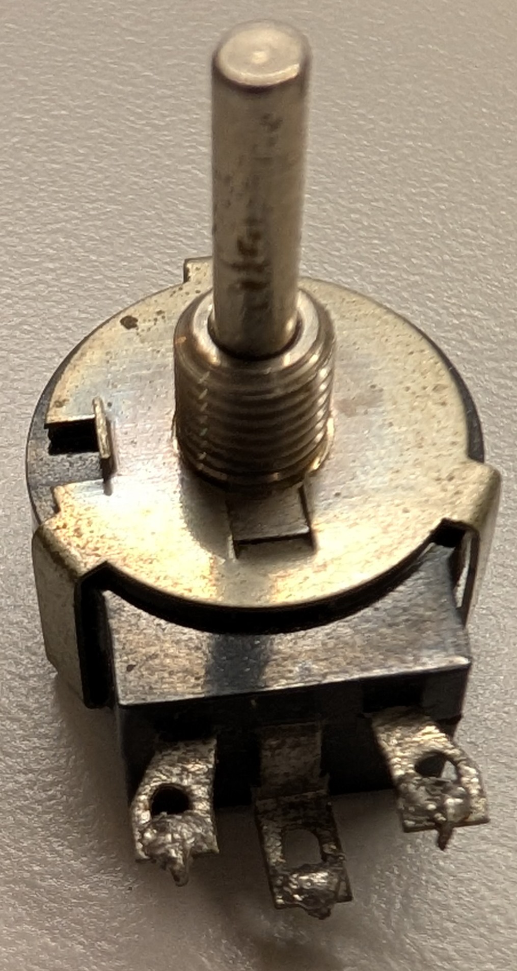
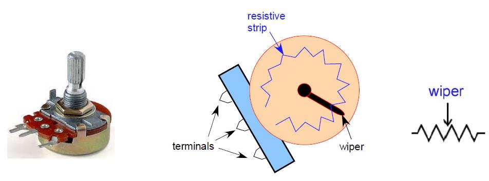
This design allows the potentiometer to be used as a variable resistor, where the resistance varies between the wiper terminal and each of the fixed terminals as the knob is rotated. Before using aany potentiometer, ensure that you are sure of the role tqaken by each of the terminals, as there can be variation in the terminal layouts.
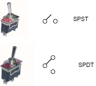
The SPST (single pull, single throw) switch has two terminals, while the SPDT (single pull, double throw) switch has three terminals as shown in Figure 9.5.6.
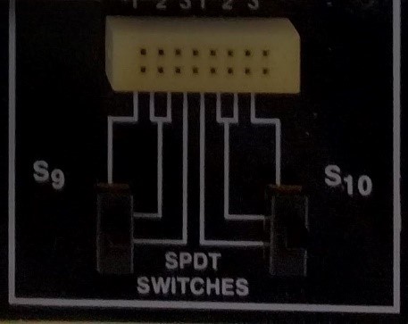
The SPST switch is meant to flip between a closed circuit and an open circuit, depending on the switch position. The SPDT is meant to flip between connection A and connection B, depending on the switch position. Always verify the switch operation before incorporating it into your circuit. Many prototyping boards have built-in switches available, as shown in Figure 9.5.8.
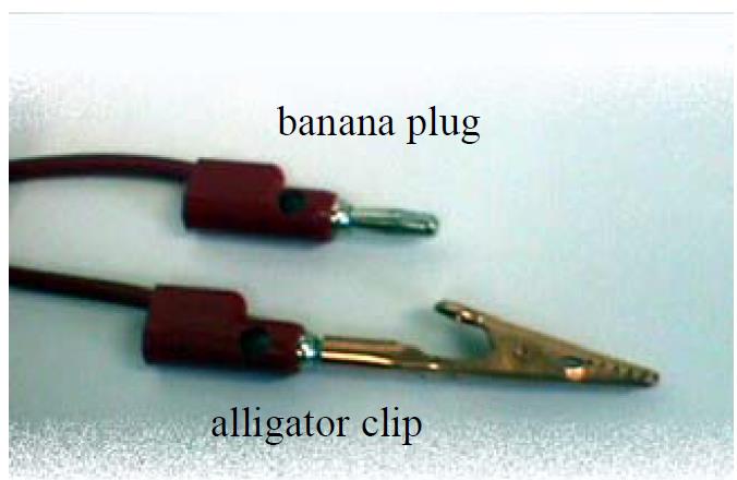
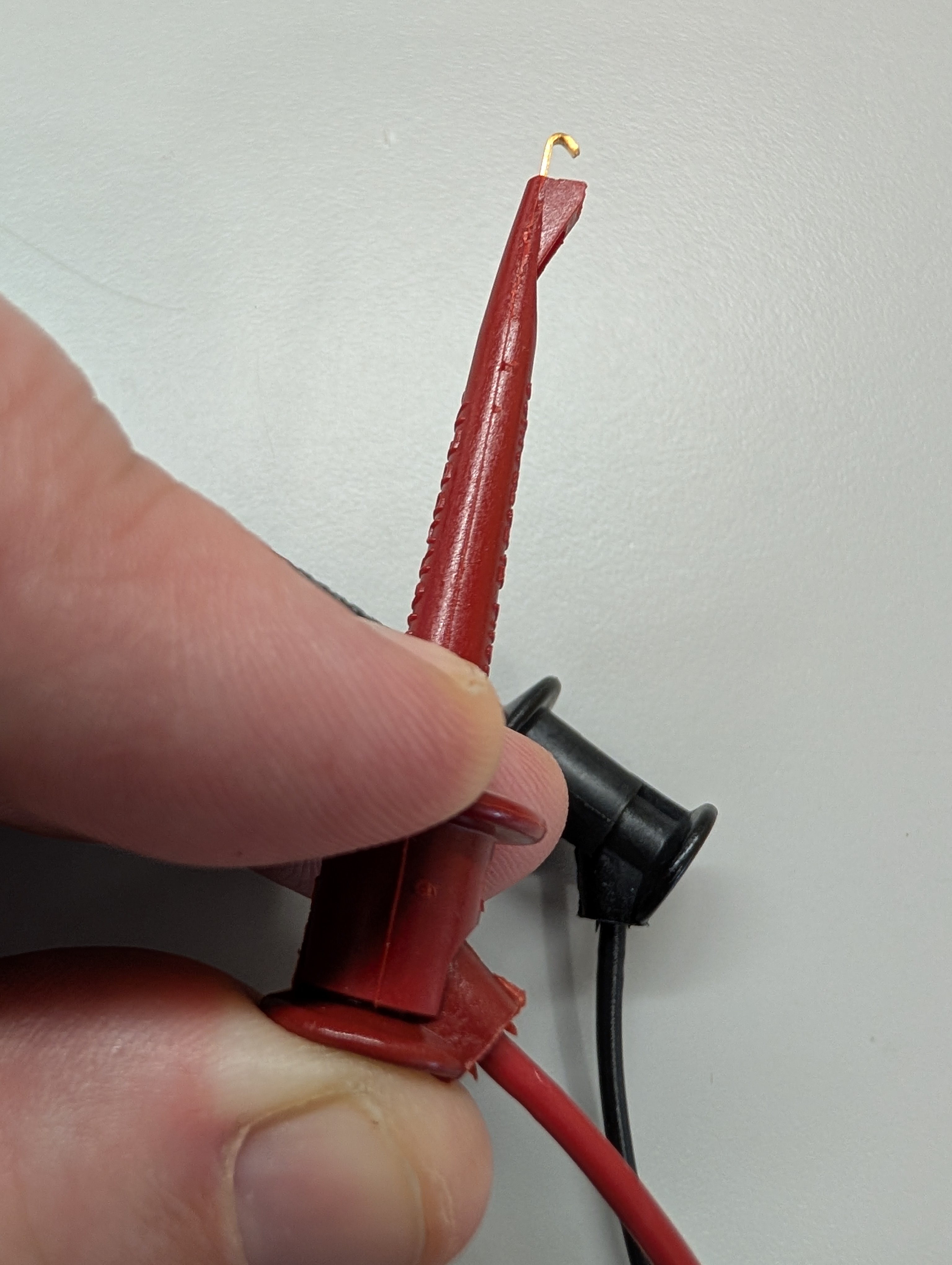
Banana Plugs (Figure 9.5.9) are typically at the ends of an insulated wire containing a single conducting path. The cable color is irrelevant to the behavior of the wires, though some thought should be used when choosing colors to assist with wiring organization. Alligator clips can be attached to banana wires, allowing them to clip to a component.
Figure9.5.9.Cable with banana connectors. There is an alligator clip placed on one of the male banana connectors.