Section 9.3 Oscilloscopes (BK Precision 2190E or 2542B)
The oscilloscope is an extremely versatile instrument. It can be used to measure both steady and time-dependent voltages, frequency, time duration, phase difference, and harmonic distortion. Some oscilloscopes automatically test transistors, perform spectral analysis, integrate, differentiate, sum, subtract, filter, and store electrical signals. Anyone working in an experimental science should be able to use an oscilloscope with considerable confidence.
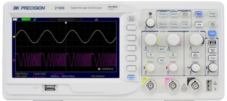
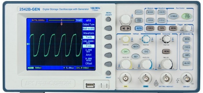
The oscilloscopes that we are using in lab (BK Precision 2542B or 2190E) are general-purpose, two-channel digital storage instruments capable of displaying and capturing electrical signals with frequencies up to 100 MHz. Its front panel can be divided into a number of sections:
-
The color LCD display shows the signal on one or more of the two input channels, using a different color for each channel.
-
A set of buttons along the right hand side of the display are used to make menu item selections.
-
A set of buttons and knobs on the right half of the instrument control some of the advanced oscilloscope functions, including:
-
a TRIGGER section that permits one to control the starting point for the displayed waveform,
-
a VERTICAL section, accepting up to two input signals and containing controls to vary the voltage resolution (among other things),
-
a HORIZONTAL or ‘time base’ section that controls the time resolution of the display.
-
In its most commonly used mode of operation, an oscilloscope creates a visual display by capturing and successively overlaying identical windows of time, each window beginning at the same point (relative to the ‘trigger point’) on the signal. The time base of the scope determines how much time is represented by each horizontal division of the LCD display. The triggering function determines when each time window is to begin; proper triggering is necessary for stable, unambiguous display of the desired waveform. Finally, the vertical section of the scope controls the amplitude of the information displayed. It determines for each of the two channels how many volts are represented by each vertical division on the display.
Hints regarding oscilloscope controls.
-
To change the horizontal (time base) scale:
-
The Time/div knob changes the time per division (sec/div are color coded by input channel and displayed on the screen).
-
Position knob changes location of the trigger (labeled as an arrow along the top of the screen).
-
-
To change the vertical (voltage base) scale:
-
Scale know changes the voltage per division (V/div are color coded by input channel and displayed on the screen).
-
Position knob changes location of the ground (labeled as a color-coded arrow on the left of the screen).
-
-
To access the parameters for each channel, press Ch. 1 (or 2,3,4) button twice and chose from:
-
Input coupling (AC/DC/Ground)
-
Invert signal
-
Probe setup
-
Bandwidth limit
-
Probe
-
Digital Filter
-
Volts/scale
-
Invert
-
-
To adjust the trigger:
-
Trigger knob changes the voltage level of the trigger.
-
Trigger MENU button
-
Select which channel to trigger off of (trigger level arrow changes color to show which channel is being triggered)
-
Slope: can trigger off a rising edge or falling edge
-
Trigger mode: Auto, Normal, other
-
-
-
To select the ACQUIRE mode:
-
Run/Stop: sets the scope to continuously acquire or freeze after the last trigger.
-
Single sequence: draws the signal only once after a single trigger. Will not trigger on successive events.
-
Autoset: scope tries to choose overall best scope settings (sometimes useful when you can’t see anything, but generally used as a last resort because it can also mislead you.
-
-
Measure menu:
-
You can select various measurements and which channel to measure. Be very careful with automatic measurements (again these can be deceptive). Generally use cursors to make accurate measurements. Note that the automatic mode searches for the very top and bottom of the signals (when measuring voltages) which may not provide an accurate value for the actual amplitude as noise on the signal may artificially inflate the max/min values.
-
-
Cursor menu:
-
Choose time (vertical bars) or voltage (horizontal bars) measurement.
-
Choose which channel to measure (measurement cursors may be the same color as the channel they are measuring).
-
Choose manual adjustment (adjust each cursor separately) or fixed (adjust both cursors simultaneously).
-
Choose which cursor to adjust (Cursor A/Cursor B).
-
Use the knob in the upper-left corner of the controls to adjust the cursor positions.
-
The position relative to ground (or trigger zero time for time measurements) is displayed on the screen with the ‘@’ symbol.
-
The relative distance between the cursors is displayed on the screen with the ‘\(\Delta\)’ symbol.
-
For further details, please read A Shortish Guide to Using an Oscilloscope, posted to the course webpage.
